Cross-limiting Control is implemented, what’s next?
The cross-limiting control schemes are utilized in furnaces to ensure the airflow never goes below the safe limit. These control schemes are designed so that whenever there is an increase in demand for fuel gas, the airflow will lead fuel gas flow, and in the case of a decrease in fuel gas demand, the airflow will lag the fuel gas flow.
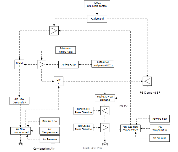
An explanation of cross-limiting control is detailed in the blog PID control: Furnace and Boiler excess air control. The schematic for cross-limiting furnace control is shown in the figure below:
Cross-limiting Control is implemented, what’s next?
The cross-limiting control scheme can be deployed in the DCS by using standard DCS blocks and calculations. The first objective is to implement the control scheme considering all override situations. The next important task for a control engineer is to tune the PID loops correctly. Otherwise, the performance of the control scheme will not be optimal and could lead to deviations in furnace outlet temperature and excess O2. There should be a balance between the tuning of the airflow and the furnace outlet temperature, as explained in the following section.
Cross-limiting control scheme tuning can be challenging
Furnace and excess O2 control are critical control schemes, as any malfunction in the furnace could affect the production of the processing unit. While tuning the cross-limiting control scheme, care must be taken to avoid spikes in the fuel gas flow. Any sudden change in the fuel gas pressure can also potentially lead to a furnace trip. In the case of cross-limiting control, the behavior of furnace outlet temperature increase and decrease are different. As one can see in the configuration, when the temperature controller demands the fuel, the fuel flow increase is slow as it waits for the airflow to increase first. But whenever there is a reduction in demand, the fuel reduces quite fast. Thus, there is a difference in process behavior in both scenarios.
Also, there is an interaction between excess O2 control and the fuel gas flow, which complicates manual tuning of these loops.
PID tuning software to your rescue
The trial-and-error method of PID tuning can be a tricky job, especially for critical and interactive PID loops. INCA Aptitune will help you to perform the tuning activity with confidence.
INCA Aptitune helps to find optimal and robust tuning parameters that will work in both scenarios mentioned above. INCA Aptitune uses a process-based open-loop model, which helps to get the optimal tuning parameters right the first time.
INCA Aptitune provides the following features:
- Optimal tuning parameters
- Reduced process oscillations resulting in less wear and tear on the equipment
- Fewer alarms and operator interventions
Do you want to learn more about our PID tuning software, how it stabilizes your plant and reduces alarms and operator interventions? Request a 30-minute live demo and gain insights into what you can achieve with INCATools PID Tuning. It’s all you need to get your PID tuning the first time right.