Every DCS has its own set of PID loop equations. A Honeywell Experion DCS features 5 different equations and an Emerson Delta-V DCS can even offer 7 equations. Each equation implies a different formulation of the PID control algorithm. So, each equation might require different tuning parameters to obtain the same or similar closed-loop behaviour. Many control engineers ignore the equation type of a PID loop. Even if you have tuned many different loops, you might not be able to obtain the desired closed-loop performance if you don’t have the right equation selected.
The reason for different PID loop equations in a DCS
There are good reasons for having a choice for different equations in a DCS. Different process responses are best controlled by using different PID equations. Also, different closed-loop objectives might require different PID equations to be used. Take for example a level control loop that is showing some oscillations in closed-loop (control engineers would call that an underdamped response). That loop is best tuned by having the gain work on the PV, and the integral action on the error (in a Honeywell DCS this would be equation C, whilst in a Yokogawa DCS this would be I-PD). This would make the response to a setpoint change a bit slower, but the disturbance rejection performance would remain optimal, which is typically the prime objective of a level control loop.
A change in the PID equation without you realizing it
Some DCS’s have a feature that will let the PID equation type for a PID loop depend on the mode of the loop. This feature isn’t well known and gets ignored most of the time. A Yokogawa DCS for instance has a PID “equation” called “Automatic Determination type 1”. For this setting, the PID equation is I-PD when the loop is in AUTO - meaning that the integral action works on the error, and the proportional band and derivative action work on the PV. But if the loop is switched to CAS or RCAS mode, the PID equation changes to PI-D and causes the proportional band action to work on the error.
This change of equation can lead to a different closed loop behavior. Let’s look at a real-life example.

Automatic PID equation change: a real-life example
Consider a fuel gas pressure controller PIC001. The fuel gas is fed to a set of burners in a furnace.
The loop was configured in a Yokogawa DCS with equation type “Automatic Determination type 1”. This means that when the loop is in AUTO mode, the PID equation is I-PD, meaning that the integral action works on the error, and the proportional band works on the PV.
The control engineer tuned the loop with proportional band 20, and integral time 3.2. This tuning results in the following closed-loop response to a setpoint change:
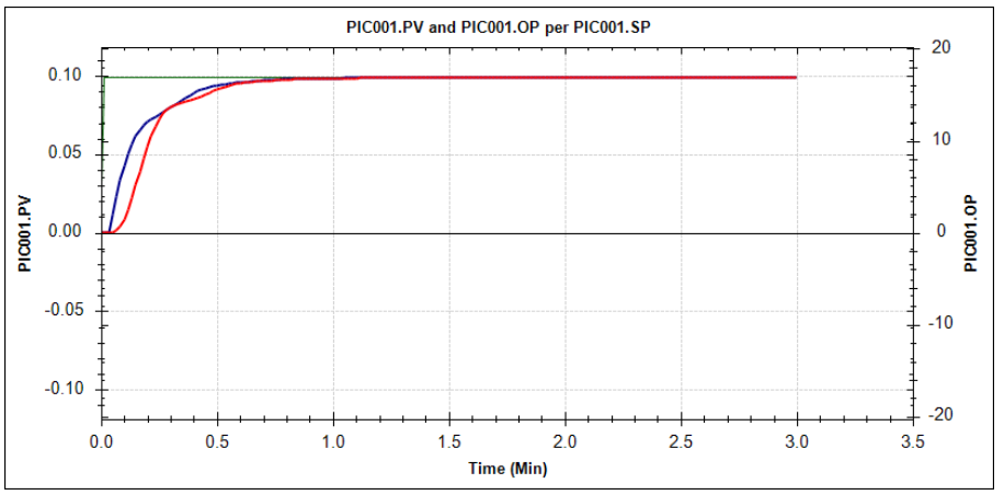
This graph shows that after a setpoint change of 0.1 bar, the PID loop controls the pressure (red line) to its setpoint nicely, without overshoot. The blue line shows the movement of the valve. As can be seen, the response is very smooth, which is important, since a large sudden downward change in the valve position could risk a flame-out on the burners.
After tuning the fuel gas pressure loop, the control engineer configured a new temperature control loop that would control the furnace outlet temperature by adjusting the setpoint of the fuel gas pressure controller. He cascaded the fuel gas pressure controller to the temperature loop.
By putting the fuel gas pressure controller in CAS mode, the DCS automatically changes the PID equation from I-PD to PI-D. Obviously, the tuning parameters stay the same. The change in PID equation causes a slightly different closed-loop behaviour:
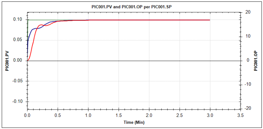
The fuel gas pressure still reaches its setpoint as fast as before (or even a little bit faster), as can be seen from the red line. But what is very different is the movement of the valve: due to the change in the PID equation, the valve now “kicks” quite significantly when the setpoint is changed. The blue line is very different from the previous closed-loop response. In the picture below, the two OP responses using different PID equations are shown together:
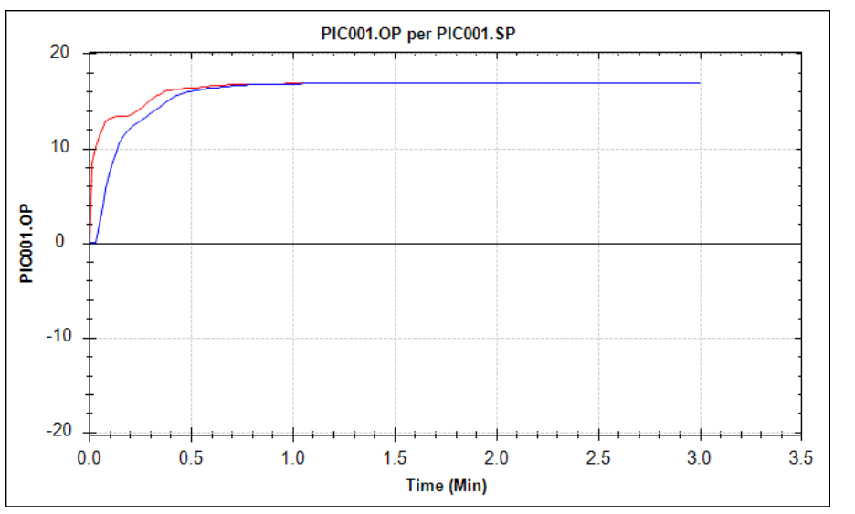
The blue line is the OP movement after a setpoint change when the pressure PID loop is in AUTO; the red line is the response after the same setpoint change when the PID loop is in CAS.
Will the difference in PID loop equations cause problems?
Whether or not this equation change causes a problem, depends on the specific case. If it would cause a problem for the above example, the solution would be simple: change the PID equation for this pressure PID loop from “Automatic Determination type 1” to “I-PD”. In that case, there’s no change in the PID loop equation if the loop goes from AUTO to CAS.
The key message here is that you should be aware that this is happening. So many DCS/Control engineers are unaware of the different equation types, and simply use the default type all the time. Let alone that they would be aware of automatically changing PID equations, depending on the mode of the loop.
PID tuning software to choose the right PID equation
The best way to analyse the impact of a change in the PID equation, is to use a software package that lets you simulate the closed-loop behaviour of a PID loop for different PID equations. Using INCA Aptitune, you can select your DCS and the PID equation simply from drop-down boxes, and start analysing the closed loop behaviour. As simple as that!
If you want to see how that works in practice, download the LANXESS case study -'Increased quality control with IPCOS process control tools'.

Do you like to know what INCATools PID tuning software can offer you?
Request your demo here.