In most of the chemical and metallurgical industries a furnace or heater is the most common and important thermal equipment used. Some control schemes have been recognized for automatic control of furnace outlet temperature, cascade control of temperature with fuel, control of fuel to air mixture ratio, and excess oxygen control content in flue gas. The design of a control scheme is very important, and it may vary as per the process and plant requirement. The final control performs well only if the underlying PID loops are designed and tuned correctly. Without robust and safe PID tuning parameters, tight and safe control of the furnace outlet temperature is not possible. Picking the correct temperature control scheme design and tuning the PID loops in it properly are equally important. In this blog you'll learn about PID tuning of a furnace.
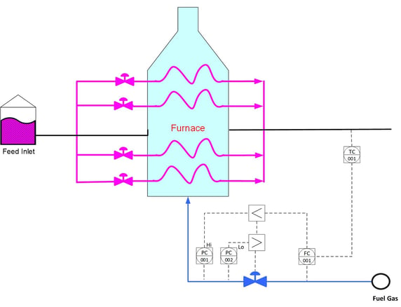
Typical furnace temperature control scheme
From the control theory literature, it's clear that having an ideal PID controller is a must for the control of non-linear processes like temperature. A PID controller in cascade with a fuel control architecture is the best choice compared to the conventional single loop control system for controlling these nonlinear processes. In the cascade scheme, the inner fuel PID loop receives the set point from the outer temperature PID loop. To protect the furnace from tripping over high or low fuel gas pressure situations, two additional override fuel gas pressure PID loops are added. Below you see the typical furnace outlet temperature control scheme:
Objectives of furnace control
In the furnace temperature control system, the primary objective is to control the temperature tightly and reject the disturbances quickly. The main disturbances are feed flow, feed inlet temperature, fuel gas calorific value and fuel gas pressure. Your main precaution that must be taken is to avoid any immediate kick in fuel gas pressure on a set point change in temperature as it may trip the furnace on high or low fuel gas pressure.You can avoid this by selecting the correct PID algorithm of your DCS which does not allow any immediate kick in the fuel gas flow and allows the PID output to land on its final value smoothly. Most of the DCS systems provide the flexibility to choose different forms of PID algorithms. It is important to mention that all these different algorithms need a different tuning.

Different PID forms and equations
Controller manufacturers arrange the Proportional, Integral and Derivative modes into different PID algorithms or structures. Choosing one of the following two forms of PID is essential during a PID loop configuration.
- Interactive Form (Series)—This form emulates traditional pneumatic-PID controllers. The controller gain effects all the three P,I and D terms. This form does not have much advantage and preferably should not be used.
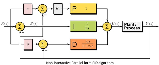
- Noninteractive (Parallel) Form—In this form, P, D, and I are added in the time domain. D is a pure derivative. This provides more flexibility when tuning difficult loops, can place complex controller zeros to cancel out highly under-damper process dynamics.
With either of the interactive or noninteractive form, you can select different combinations of proportional, integral, and derivative control terms. These combinations are as follows:
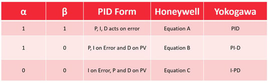
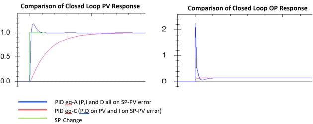
- P,I,D on error (PID or Equation-A): All the three terms act on error (SP-PV).
- P,I on error and D on PV (PI-D or Equation-B): The proportional and integral terms act on error (PV - SP) and the derivative acts on PV changes. This equation is used to eliminate derivative spikes in control action that occur with quick changes in the setpoint.
- I on error P and D on PV (I-PD or Equation-C): The integral term acts on error (PV - SP) and the proportion and derivative terms act on PV changes. This equation provides the smoothest and slowest response to setpoint changes.
Selection of the correct PID Algorithm
By default, many DCS PID algorithms are set to interactive ideal PID algorithm (P, I and D on error) purely for historical reasons and in 90% of the cases people do not change it to some other algorithm. One disadvantage of the ideal configuration is that large changes in setpoint will cause the proportional and derivative term to become large and result in a “ large kick” of the final control element (Fuel gas flow).
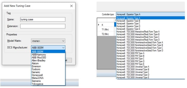
An alternate implementation is to set the proportional and derivative mode to act on measurement changes (PV) and not on the error between the SP and PV (P and D on PV, I on error). For furnace temperature control, it is recommended to select the “non-interacting” PID algorithm (P and D on PV, I on error). Different DCS vendors use different ways to select this algorithm. Honeywell DCS for example, refers to this algorithm as “equation-C”. Non-Interactive (Parallel form) equation provides more flexibility when tuning difficult loops and can place complex controller zeros to cancel out highly under-damped process dynamics.
PID equation C (I_PD) does not contribute to the OP kick but does help with damping out the OP to reduce PV overshoot and cycling. The OP will NOT KICK after a set point change despite of aggressive tuning; The PV response is normally slower. In case you are not using a derivative term, then PID equation-B (PI-D) will result in the same response as PID equation A (PID).
Optimal PID tuning with a first-time-right approach
Once the correct PID algorithm and PID equation have been set, the next step is to find out the robust PID tuning parameters. Trial and error is a simple but time-consuming process with no guarantee of success. On the other side, some people use tuning rules like Ziegler-Nichols, Cohen-Coon, Lambda and Kappa-Tau which give reasonable results in many (simple) cases but they assume linearity, are limited to ideal PID algorithm only and no control objectives like PV Overshoot or OP kick can be defined in these tuning rules. So again, no success is guaranteed.
PID tuning software like INCA AptiTune enables you to tune your PID loop by choosing the correct PID algorithm and available equation of your DCS.
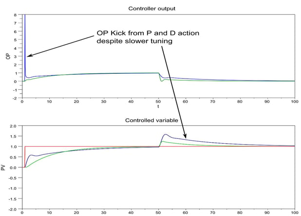
A comparison of the different tuning methods on a furnace temperature controller is shown below.
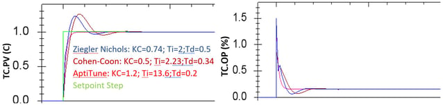
A selection of the proper PID algorithm together with PID tuning parameters is very important for your desired results. The response with the same PID tuning parameters is very different with different PID algorithms. In most of the DCSes, the default PID algorithm is set to interactive with P,I and D on the error. People do not change it often. PID software like INCA AptiTuneTM enables you to simulate the PV response with different PID algorithms to choose the one satisfying your requirements. For furnace temperature control where we cannot afford any immediate kick in the fuel gas pressure, it is recommended to choose the Non-interactive PID equation with P and D on PV and I on error. AptiTunealso allows you to set many control objectives like PV overshoot, OP kick, damping ratios etc. Itwill calculate the right parameters and you don’t have to look at it again. In the end, the software helps you achieve the desired result faster.
With a first-time-right approach — using PID tuning software — you get:
- Reduced process oscillations
- Safe and smooth landing of PID output
- Fewer fuel gas pressure alarms and operator interventions
Read the case study below on tuning a duty controller on a reformer

Do you like to know what INCATools PID tuning software can offer you?
Request your demo here.