Buffer tanks are built to provide smoother operation to the process, avoiding the propagation of disturbances on the inputs, e.g., temperature, composition, feed rate, to the downstream process. Aggressive tuning methods don't work for buffer tanks since you want to explore the largest volume possible to reduce the disturbances. In this blog, we will explain how you make a compromise with the correct tuning.
PID tuning for Buffer tanks
To be able to reduce these disturbances, the PID loop must allow the level to move up and down, accepting a certain “error” between the PV and the setpoint. By temporarily allowing the level to change, the variability in the inlet stream is dampened inside the tank, reducing the disturbances to the outlet.
When setting a tuning for a buffer tank we want to explore the largest volume possible, so we reduce the disturbances as much as we can. However, if the disturbances are too big and the tuning is too slow, we may overflow the tank, which is never an option in process industries. On the other hand, if the tuning is too aggressive, the buffer volume will not be used, and the disturbances will be propagated without damping, causing the downstream process to oscillate. And that is also not a good way out.
6 important aspects when tuning a buffer tank
Integrating processes do not reach a steady-state from a stepwise input. For this reason, there are important aspects to be considered when applying the PID tuning recipes, such as being more careful when it comes to step testing the process and choosing only suitable rules for integrating systems (e.g., Lambda, or Zak Friedman’s averaging level rule).
The case studies "Best PID tuning methods explained for level loops" Part 1 and Part 2 explain the different tuning methods and the results for levels with different objectives.
Apart from the tuning rules, some important aspects can be easily considered when tuning the buffer tank, as below:
- If a flow controller is used as slave loop, be sure it is properly tuned before the level is tuned (you can also check how to tune cascade loops here ).
- Know beforehand the size of the tank, and the location of the 0% and 100% level measurements.
- Check the setpoint for the level controller in normal conditions and the limits within which the level should be kept from a safety point of view.
- Look at the historical data to check the common disturbances the tank is subjected to. Consider “normal” operation data only, as the changes during starting-up procedures are normally controlled by operators or dedicated PID loops.
- Based on the available volume around the setpoint, and the variations the inlet flow is subjected to, we set a first estimate for the controller gain, from Zak Friedman’s rule, or the lambda value to be used in the Lambda tuning approach.
- Remember that as the non self-regulating process adds the “integral” action to the response and low integral action is normally required.
- Step test the process in open loop to get the process model if needed.
With this approach, an initial tuning can be easily obtained, but the performance of the loop would be uncertain. Finding the right set, will require some iterations, which can result in a lot of time spent, especially because of the slow dynamics involved, and risks to safety. The trade-off between letting the level to vary within limits and increasing the oscillations to the downstream processes will not be easy to solve manually.
You need a robust tuning set that considers a larger volume
 A robust tuning set should guarantee that changes to the process will not cause the system to oscillate or become unstable. In a buffer tank, these can be easily associated with changes in the downstream pressure, or in the inlet flow, for example. A robust tuning for a buffer tank should consider the larger volume to be used for damping the inlet disturbances, but with some safety margin for changes in the process.
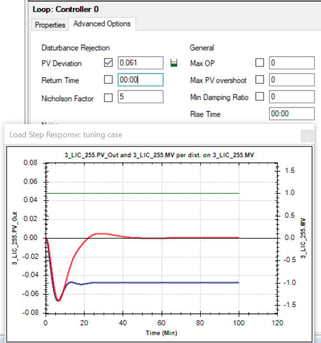
With AptiTune you can set engineering specifications to be met, as maximum PV deviation, or the return time, and test different scenarios when designing the tuning for your buffer tank. The robustness of each set can be easily verified via the Stability Robustness Plot, supporting the PID loop tuning procedure, and saving you time.
Want to know more about how INCA AptiTune can help you to “smoothen” the task when tuning a buffer tank: push the bottom below and request a live 30-minute demo with a PID tuning expert.